Design
-
UAV Payload Competition - CAD, FEA, Fabrication of a Drone Frame
-
Determining Tolerancing, Fits, Machinery's Handbook - Clampable Desk Organizer Product
-
Evaluating Solutions of a High Altitude Balloon Parachute Release Mechanism
-
Solid Works CAD - Creating a Ball Launching Mechanism for Dogs
-
Creo Parametric CAD - Modeling a Garbage Truck Arm Mechanism


UAV Payload Competition - CAD, FEA, Fabrication of a Drone Frame

Skills learned:
-
Learning to work with a busy team, and managing our time
-
Bouncing ideas to make a final, optimized design
-
CAD using Fusion360
-
GD&T drawings using Fusion360
-
FEA using Fusion360
-
3D printing, and practical limitations
-
Soldering wires
-
Documenting work
Project Website:
In the College of San Mateo's Engineering Graphics class, my group and I were assigned a final project. The goal was to utilize our knowledge of engineering drawings and use CAD software like Fusion360 to practice GD&T, good design, and to do FEA. I practiced learning how to create engineering drawings, follow GD&T and linear tolerancing conventions, and modeling/assembling/simulating my team's designs using Fusion360.
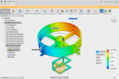
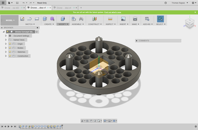
We were tasked with creating a drone frame that would be tested in the real world. Our drone would be tested by competing with other students to see which drone can lift the most payload. Besides the competition goal, our drone frame had to pass the design requirements
-
Having a deflection of only 10 microns in Fusion360's simulation
-
For the drone frame to be 3D printed
-
Demonstrate how our drone frame was designed to not only be sturdy but light in weight
-
To show how we used Fusion360's modeling tools and trial and error to show how we optimized our design
My contribution was the following:
-
Assisting with the design process from V1 to V6
-
Assisting with CAD design suing Fusion360 to create/modify the drone frame
-
Performing FEA to test deflection due to a payload
-
Testing tolerances of the battery and motor holders, using calipers
-
Creating the website
Determining Tolerancing, Fits, Machinery's Handbook - Clampable Desk Organizer Product


Skills learned:
-
Teamwork and communication in an online setting due to Covid-19
-
Referencing the Machinery's Handbook to decide fits, tolerances, and grades for a specific part
-
Referencing the Machinery's Handbook to decide appropriate manufacturing processes based on the grade for a part
-
Determining process selections for high volume manufacturing
-
Utilizing each person's unique skills and interests to design a product
The Goal of The Project:
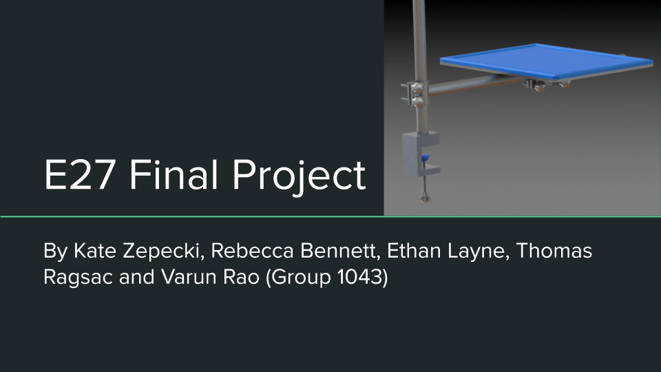
To design a product that mounts onto an external object, in addition to being practice for specifying fits, tolerances, grades, and drafting engineering drawings using SolidWorks. In addition, my team was expected to use our specified tolerances and what we learned about high volume manufacturing.
Reflection:
It is amazing to see what my project mates and I achieved during a semester with Covid-19. I am grateful to have been able to work on a project with teammates who were understanding of each other's personal situations with Covid-19. Without everyone's effort, the final product would not be what it is now.
I am glad to have team members who were all skilled in certain areas where I was not and for my team members to be patient enough with me to practice new skills. While some of the members created CAD drawings and the engineering drawings, I was the one who referenced the machinery handbook to specify tolerances and double-check compatible manufacturing methods. The graduate student instructor and professor's advice was also very helpful when we could not progress. I do not know what we would do without digital tools like Zoom, Facebook Messenger, Google Drive, and GrabCad.
In the end, we were able to have a final product with engineering drawings (exploded, detail, and layout), parts with specified fits and tolerances, and manufacturing processes and material selections for each part.
Tasks Achieved:
-
Using the machinery's handbook to determine the tolerances of a part needed to achieve fits specified by the other team members Fits table in the final report
-
Using the machinery's handbook to determine the grade and compatibility of a manufacturing process based on the specified fits by other team members in the Fits table in the final report
-
Double-checking the grades list checking for the working drawings document with our working drawings
-
Writing the differentiation section for how our clampable desk organizer in the final report
-
Writing the justification of the manufacturing process selection, design for manufacturing, and material choice section of the final report
Evaluating Solutions of a High Altitude Balloon Parachute Release Mechanism
Skills learned:
-
Researching previous solutions designers have tried
-
Extracting significant information from research papers
-
Synergizing theory learned in class with preliminary research
-
Presenting findings to a team via PowerPoint
This project relates to being part of the club Space Technologies At Cal (STAC) when I attended the University of Calfironia - Berkeley. The goal was to deploy a High Altitude Balloon that would be a vehicle for scientific projects. I was part of the Mechanical Engineering development, specifically creating a release mechanism for the parachute that would inflate when the balloon popped. I joined for one semester during the early year of COVID-19, and in that time I did preliminary research of mechanisms and my proposed solution. I then presented my solutions to the club.
Solid Works CAD - Creating a Ball Launching Mechanism for Dogs


Skills Learned
-
CAD - Solidworks
-
Modeling Parts and Assemblies
-
Motion Analysis
-
Force Analysis
-
-
Communicating with a team with diverse skills
The Goal of the Project:
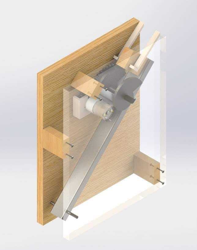
To create a planar machinery device that has the purpose to help people throw balls for their dog.
The design is based on a CAM extending a spring. As the spring extends, a lever arm is pulled back until the lever arm collides with the ball. The mechanism is supposed to have an automatic ball feeder, but we were not able to get that far.
This project was a great experience for me because I felt that everyone had a unique skill and task for the project, and the combination of our skills and teamwork led to a product that launched balls. I focused on the CAD, but I got to learn about manufacturing, component searching, and the business/advertising part by working with the other members.
Things achieved:
-
Learning how to do prior research
-
How to create product specifications as a basis for the product
-
Learning how to use Solidworks
-
Learning how to buy on McMaster
-
Learning how to create a good presentation
-
Reflecting on better design choices in retrospect
PTC Creo Modeling Example Work -
Dimensioning for Manufacturability, Family Tables, Parametric Modeling


Skills Learned
-
Proper geometric constraining
-
Dimensioning with DFM in mind
-
Using family tables to parametrically dimension features
-
GD&T with PTC Creo Parametric
In the class E128, some of my first assignments were to create parts based on the intended dimensions given.
When learning how to parametrically model parts in CREO, we learned how to do this with family tables.
I learned dimensioning parts correctly with a design for manufacturing (DFM) in mind is important to do for the first time, instead of having to change dimensions later in the manufacturing process.
Creo Parametric CAD/3D Studio Max - Modeling & Animating a Garbage Truck Arm Mechanism


For the final project of the class, we were asked to model a complex mechanical system in Creo Parametric and animate our CAD files for technical communication.
My project group goal was to model the Durapack Python Automated Sideloader Garbage Truck developed by Heil. Our group of four divided the work between the half of us, so two of us CAD the truck, and two of us CAD the sideloading arm.
My project partner and I CAD the arm portion.
Skills Learned:
-
modeling/dimensioning parts based off of a picture reference
-
modeling parts so the main features are modifiable in the future
-
working with a team of 4, and dividing work between subteams
-
communicating with my partner and building parts based on each other's parts
-
animating the arm mechanism in 3D Studio Max